1.0 I thought it might be useful to give some insight as to how the Bloodhound System operated so I will run a series of brief lessons using, wherever possible, original training notes. So, starting right now, here is Lesson 1 – Overall System Control and Operation (OSCOP).
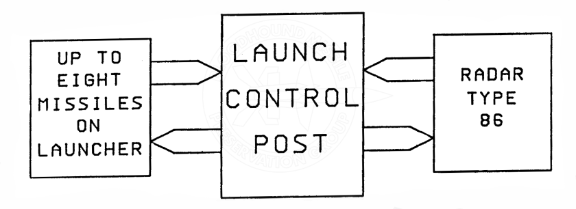
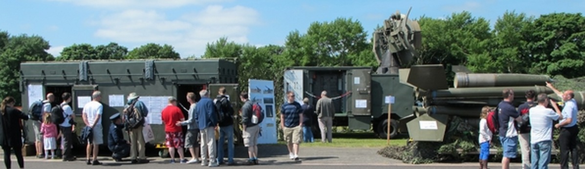
1.1 The Launch Control Post (LCP) is the heart of the Bloodhound Missile Section. It is from the LCP that the Radar, Missile and Launcher combinations are controlled during operations. Note that wherever the Radar Type 86 is shown this could have also been a Type 87 as both were used by the Royal Air Force.
1.2 We will look at the Radar to LCP sub-system first.
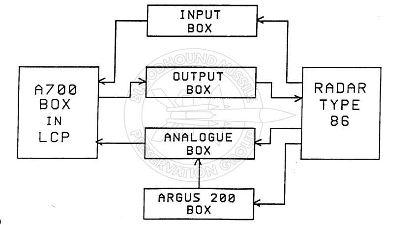
1.3 Almost all information to and from the Radar is processed by the Ferranti Argus A700 computer (Processor Box). The diagram below is a simplified representation of the Radar to Processor system in the LCP which handles the input and output signals.
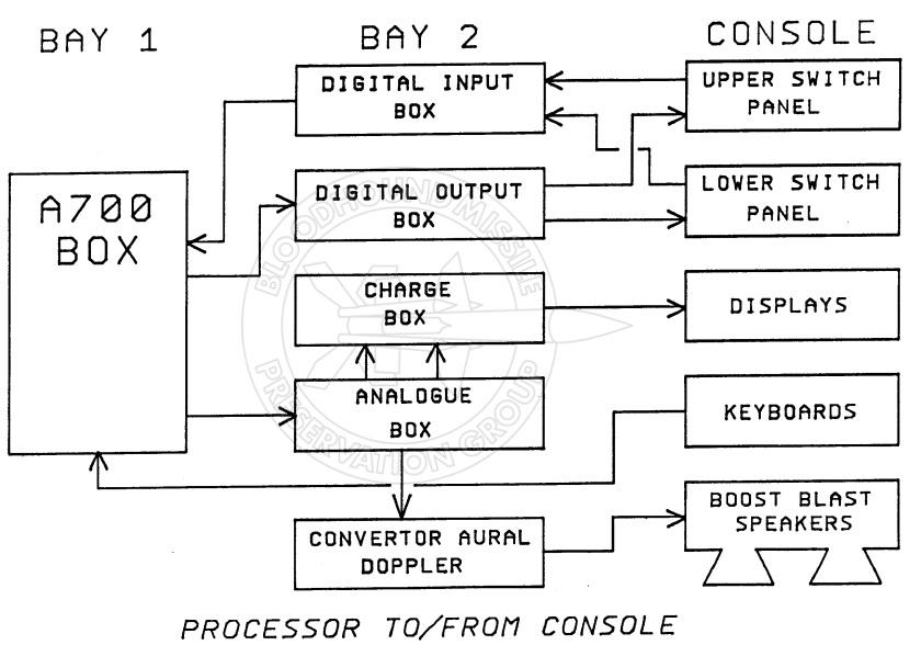
1.4 The Processor Box also communicates with the LCP Console. The diagram below is shows the Processor Box / Console system.

I fear from your block diagrams that you will alienate a lot of past Bloodhound men with your reference to T86 only what about the T87? Rob Findlater
WordPress.com | bmpg posted: “1.0 I thought it might be useful to give some insight as to how the Bloodhound System operated so I will run a series of brief lessons using, wherever possible, original training notes. So, starting right now, here is Lesson 1 – Overall System Control ” | |
LikeLike
Than you Robert. I have picked up on your observation and have added a note in text that that both T86 and T87 were used.
LikeLike