Hi folks, this posting is a bit of a catch up on a couple of previous weeks as well as this one.
LCP
Mode Change Not Allowed…. the fault still exists after another fruitless day trying to fault find in the LCP. The decision was made on last Saturday to remove the Digital Input box from the I/O rack and check it out in the workshop. It is now obvious that trying to fix this fault without known good spares is almost mission impossible. We have spare cards for the Digital Input box but as-recovered not as-issued from the manufacturer or third line – those were the days.
The plan is to test all the input cards in the workshop and several faults have already been found including a Serial to Parallel Converter that permanently activated data bits 2 and 3 irrespective of the Digital Input box addressing and irrespective of data being read from the corresponding inputs. Still no joy though when that fault was repaired (a faulty 74S04 TTL device – what is it with these most basic of TTL ICs as we have had LS04 failures too?).
All sorts of issues were experienced on Saturday such as the +5v increased to +6v on the Digital Input box when cards were removed. Luckily no obvious consequential damage but it did create havoc with the timing on the cards in the Digital Input box.
Working on the Digital Input box ‘standalone’ in the workshop using our PeriBus test set allows the addressing of individual input cards and the reading inputs from them. We can then sign-off good cards and not be misled by additional faulty cards being used in the Digital Input box which we assume to be ‘S’ spares when in fact they are U/S.

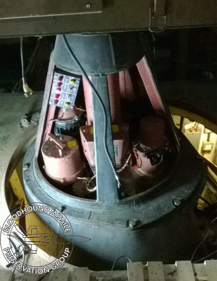
The photo above shows the test set up in the LCP. Waveforms and voltages are displayed on a laptop using a PicoScope (USB oscilloscope), great bit of kit. I’ll never use a standalone oscilloscope again. The two LED’s extinguished on the extended input card are LED’s 22 and 23 indicating (correctly) that the A and B Reload/Available switches are in the correct Reload position for running the simulator. The evidence in the LCP for “Mode Change Not Allowed” fault is that all relevant switches are operated and indicated by their LED’s on the Digital Input cards but the Argus is not seeing any inputs from the Digital Input box on the Serial PeriBus, disconnect the Serial PeriBus from the Digital Input box and the fault stays the same.
A further problem last week was that a 15V 16A power supply blew one of its paper filter capacitors, lots of smoke and a horrible smell. Replaced the power supply with a spare. We thought all the power supplies installed in the LCP had their paper filter capacitors replaced as a matter of course, obviously not!
T86 Radar
Neil succeeded in lowering the Aerial pedestal a few inches after a few weeks of trying ways to get the retraction chain moving on the cogs that wind down the pedestal; he was ably assisted by Dave S, or is it the other way around? Anyway, we can now hand crank the pedestal up and down manually with the retraction gearbox which required some major refurbishment. We needed to be able to retracts the pedestal for corrosion treatment and to check the seal between the pedestal drain trough and the cabin roof. Lowering the pedestal with the aerials on their back allows for better access to the aerials for refurbishment.The photos below give two views of the pedestal lowered, the top one is from the cabin roof, the bottom one is from inside the rear of the T86 cabin looking up at the roof aperture.