Bloodhound System Lesson 1 Overall System Control and Operation

1.0  I thought it might be useful to give some insight as to how the Bloodhound System operated so I will run a series of brief lessons using, wherever possible, original training notes. So, starting right now, here is  Lesson 1 –  Overall System Control and Operation (OSCOP).
BMSMS-OSCOP1a wm.png

1.1  The Launch Control Post (LCP) is the heart of the Bloodhound Missile Section. It is from the LCP that the Radar, Missile and Launcher combinations are controlled during operations. Note that wherever the Radar Type 86 is shown this could have also been a Type 87 as both were used by the Royal Air Force.

1.2   We will look at the Radar to LCP sub-system first.

1.3  Almost all information to and from the Radar is processed by the Ferranti Argus A700 computer (Processor Box). The diagram below is a simplified representation of the Radar to  Processor system in the LCP which handles the input and output signals.

BMSMS-OSCOP1b wm.png

1.4  The Processor Box also communicates with the LCP Console. The diagram below is shows the Processor Box / Console system.

BMSMS-OSCOP1c wm.png


Work Day 17th February 2018

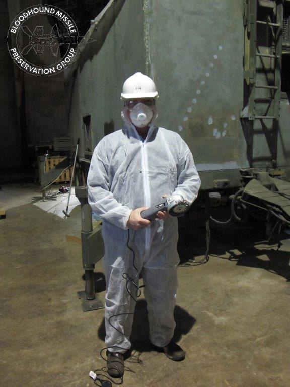
A three man restoration crew today and all still agreeing over a cuppa that if we didn’t make the effort then a key part of the UK’s Cold War heritage would disappear! This week the day’s work was entirely on the T86 radar trailer.

T86 Cabin Floor
Almost there with prepping the floor for a repaint, these jobs always take longer that you think! Pete J abraded the alloy floor with a sander to give a finish ready for painting.

T86 Cabin Floor Ready for Painting wm.jpg

But there is still one more job before paint is applied and that is to replace a number of wasted rivets.

T86 Cabin Floor Corroded Rivets wm.jpg

Dave also spent most of the day in the rear of the T86 cabin (he drew the short straw) on yet more scraping and prepping of the floor.

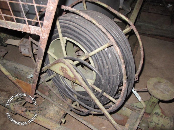
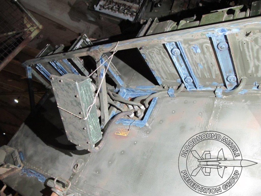
T86 LCP/LCP Simulator Switch-Over Box
This is a unit that should be screwed to the floor in the rear cabin, adjacent to the cable inlet. It is not screwed down any longer, it has become a lose item as the floor had rotted away and was hindering Dave’s work in the rear cabin. The unit, shown in the accompanying photo, was unplugged and removed. The photo shows the unit as removed, it has subsequently been cleaned and now looks like new (ish). The change-over box was possibly part of the mod program when the MK2A LCP was introduced in the mid 80’s.

T86 LCP - Sim-Switch Over Box 2.jpg

T86 Coolant Chillers
The T86 has three chillers and when the chassis was being cleaned it was noticed that the two chillers on one side were disconnected. As we are in the process of refurbishing the cabin it was an opportunity to remove these and check for corrosion and any other problems. Two accompanying photos show one of the chillers being removed and the ‘holes’ that were left. Dave then set about cleaning, scraping and treating corrosion, which was only minor (the corrosion not Dave’s work).

T86 Removing Chillers wm.jpg

T86 Chillers Removed wm.jpg

T86 Pedestal Roof
The pedestal roof is the only part of the T86 cabin that is constructed from thin, mild steel, sheet. After many years in the open water was allowed to collect on the pedestal roof, the steel roof has severe corrosion in a few places. The accompanying photo shows the worst roof section and the corrosion damage.

T86 Corroded Pedestal Roof wm.jpg

Obviously this section needs cutting out and replacing but we do not currently have the resources or the kit to carry out such a replacement repair. We would be so grateful if some kind individual or company could help us; is anyone out there able to offer to do the job for us please?

As we are currently focused on getting the cabin prepped for repainting it has been decided that such a job will be put on the list of ‘big jobs to do in the future’. In the meantime a temporary metal plate will cover the affected area to seal and protect from any possible water ingress.

For now it will be a temporary solution of plating over and sealing the corroded through area until such time as we can do a proper job. In fixing a plate to the pedestal roof we also need to ensure that we do not create a water trap. There are sections of the pedestal roof where it overlaps the cabin wall that should also be cut out and replaced, again a job for the future.

…… back again soon!

Work Day 10th February 2018

T86
It couldn’t be put off any more! The time had come to make a start on prepping the T86 chassis, removing corrosion, loose paint and dirt from underneath the cabin. A job that no one in their right mind would volunteer for, but needs must. The accompanying photo shows Pete H dressed for the occasion and before anyone comments, gloves were worn when the job started. While some corrosion exists, particularly on the leaf springs, the under cabin condition is not too bad.

Pete H Dressed for T86 chassis wm.jpg

Neil refitted the elevation motor. The motor was removed a couple of years ago so a corroded baffle could be removed as it was preventing the aerial assembly from moving in elevation.

Ian was busy lifting the now completed new plywood floor and scraping the metal floor of the cabin ready for priming. The plywood will also be treated with preservative before refitting. The floor will be completed when new vinyl is fitted, a close to if not a direct colour match (mucky green) will be made.

Pete M used his impact driver to remove the remaining cabin fittings, i.e. reflectors and cable clips. External cables on the cabin are covered in a metal mesh tube which has badly corroded so has to be removed. The cabin reflectors are discoloured and the rubber mounts perished. All will be replaced in time.

Two photos are attached for interest. When we recovered our aerial cage it only had two original items in it, the base plate for the collimation tower and its cable. Where the rest of the collimation tower is, or went to we have no idea. The photo of the base plate may confuse as the mounting bracket for the aerial assembly lifting frame is resting on it.

T86 Collimation Base Plate wm.jpg

T86 Collimation Cable wm.jpg

LCP
The simulator was run up and remains serviceable which gave Pete M the opportunity to make a video of a Class 3 kill which is when a target is not totally destroyed by the missile’s warhead but damaged so that it takes a period of time before coming down to earth.

Work Day 3rd February 2018

LCP
The simulator was given a run following a couple of weeks when it wasn’t checked. Happily all remains serviceable.

T86
More of the same. Prepp’ing the T86 cabin and aerial system for a repaint. Two photos below showing the treatment of corrosion on the Ward Leonard shelves:
T86 Corrosion Treatment wm.jpg

and the top of the pedestal where the corrosion was rubbed down but not yet treated:

T86 Corrosion on Ae Assembly wm.jpg

Once the corrosion treatment has done its stuff an anti-corrosive primer will be applied. Note that the corrosion treatment is blue, the colour when it is still wet, when dry it turns black.

One challenge on the aerial assembly is how to get at all the awkward places to rub down as many gaps are too narrow to get your hand in. Never mind, we’ll find a way. A discussion was also had on the colour of the paint used on the aerial reflectors as it’s certainly not NATO Green. It looks like the original colour applied to the Swedish Bloodhound kit, or at least the radar. We also discussed how to treat the several paint blisters on the front of the transmitter aerial.

Included with this blog is a photo of a sight that all T86 guys will be familiar with it shows the indicators in the pedestal when the aerials are in one of the azimuth end stops, in this case the anti-clockwise end stop has been activated.

T86 In the end stop wm.jpg

In an operational radar the aerials in an end stop usually indicates one or more of the power transistors in one of the drive amps in E Rack has gone. We, on the other hand, managed to accidentally push the aerials in to the end stop. So that we can move the aerials we have had to patch in a -24V supply to remove the brakes when required. There is no plan to drive the aerials using the Ward Leonards and the drive motors; well, not unless someone has a 3-phase supply and that other commodity – money.

In the Workshop
Work is in hand on bench testing a faulty A700 memory card, capacity is 1 Mega Byte! The card has two PCB’s, a mother and daughter arrangement holding a large number of 4864 memory chips (64K x 1 DRAM) and the control circuitry. The memory card and its edge connector ‘adaptor’ is shown below. Bear in mind we have no board test equipment, not even a design specification, let alone a test specification! More information on testing and fault finding this card will be covered in future blogs.

ME147 Test Bench wm .jpg