T86
The plan is to complete all the prep work for a repaint of the T86 this summer still holds good. The work being undertaken is thorough and includes the removal of the cabin wheels and treating the chassis corrosion.
Wheel removal
Removal of the wheels from the cabin has proved to be challenging, that is until a torque multiplier was acquired, Pete M’s comment was ‘this is a dream’ following previous weeks that were spent creating all sorts of leverage systems to try and release the wheel nuts. Here shows the torque multiplier in action.
 Once the wheels are removed lose paint and corrosion is removed from the wheels, leaf springs, brake drum etc, all becoming much easier. Pete M in action on a leaf spring below.

The T86 cabin wheels are in a poor condition due to their age and the extended period the cabin has been in the open. The tyre rubber is perishing and corrosion on the wheel hubs is severe but not terminal. The accompanying image shows the inside of wheel after removal, not much paint left and a decent amount of vegetation! The T86 cabin will not be made road worthy as it does not comply with current vehicle regulations etc. but it will still need moving short distances and the perished tyres will not be suitable for that purpose in the longer term. We are therefore on the lookout for part worn 10.00 15 tyres – please anyone?

Replacing the cabin floor
Dave and Pete J have replaced the front cabin floor which can be described as a precision job. The first image shows the floor fitted before moving on to priming. To complete the new floor the lino, or a more modern version of, will be laid over the wood with metal fillets to cover joins on the wheel arches.


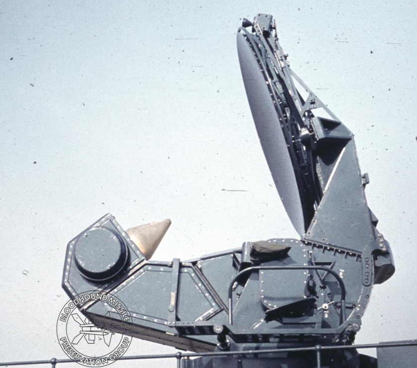
Preparing the aerial assembly
Neil continues with what looks to be a never ending task of rubbing down all the aerial system components and the rats nest of the wave guide assembly. Here is Neil being ‘embraced’ by the aerial system!
Refurbishing components
Many of the smaller components are being refurbished off site as they are easily transported! Two accompanying images show the handles for the receiver cover and the pedestal support pillars from the rear of the cabin, before and after paint stripping.


F16 (400Hz) Power Supply
We gave the power supply a good soak test on Saturday by connecting its output to 115V incandescent bulbs; it ran for several hours without a problem. ge. At a date to be decided a test run of driving a few synchros will take place.

LCP
After several weeks of being U/S the LCP (simulator) was run up and as per last week remains serviceable with the exception of a vertical sync issue on one monitor which has been shelved to get on with other work.
Pete H


 The next stage is to fix these panels to the cabin floor. All panels are secured in place by being bolted through the floor, new bolts have been procured as the originals were completely corroded and had to be cut out. The forward section of the cabin floor was also painted ready for the refitting of the wooden panels. The accompanying photo shows the repainted cabin floor, apologies for the poor quality image it will be replaced next week.
