Work Day 29 July 2017


LCP Cabin
A long outstanding job was completed on the LCP cabin, the rubbing down of the cabin rear wall ready for painting. Next Saturday the rear of the cabin will be primed before a final top coat is applied.

Type 86 Radar
We need to ‘hand crank’ the aerial pedestal retraction mechanism to check the pedestal seal is OK with the underside of the cabin roof. We will also need to fully retract the pedestal to move the T86 at some time in the future. Problem, the mechanism is seized. The pedestal motor and the gear box that drives the chain for winding down the pedestal has been exposed to the elements and hence corrosion the likely cause. It is not required that the motor ever works again but the gearbox must be usable.


T86 Pedestal Motor.jpg

The motor was removed and the next check revealed the gear box (below) was seized (probably the motor as well). It was a struggle to split the gear box which confirmed the damage done by water ingress.

T86 Pedestal Motor Gear Box.jpg

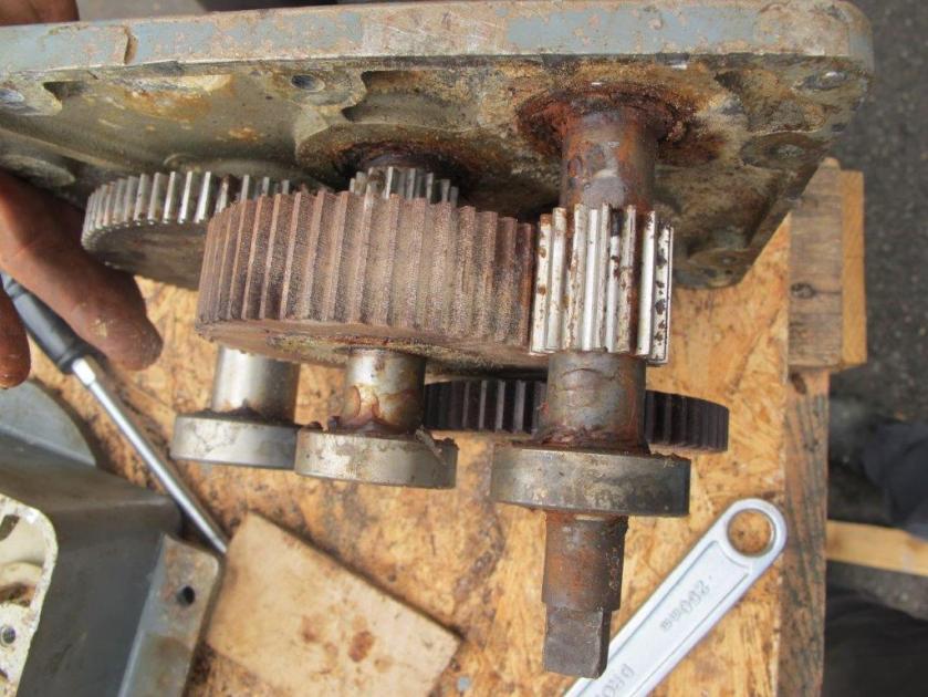
When the T86 was recovered the pedestal cover above the retraction motor was not sealed so water simply ran down the pedestal, under the cover and on to the retraction motor. Work now starts on refurbishing the gear box so the pedestal can be hand cranked. It was interesting to find that two gear wheels were made of paxolin so when the pedestal retraction was driven by the motor and if the limit micro switches failed then the paxolin gears would strip preventing the motor trying the drive the pedestal though the radar roof or floor.

Work has also started on preparing the aerial system for a repaint so it is the usual removing of lose paint, corrosion treatment, filling and rubbing down before we get anywhere near a paint brush! Neil is hard at it again!

Prep on T86 Ae.jpg

Bloodhound 2 – Non-Coherent Jamming

A little while ago Pete Murray asked whether the Type 86 was vulnerable to non-coherent CW jamming. I reported in the Work Day blog for 22nd July that he tried it out on the simulator and it appears that the radar can be jammed by an non-coherent jamming signal at the skin echo frequency. As promised here is that more detailed report.If the jamming signal perfectly overlaps the skin echo, the radar will not acquire the jamming signal (as it fails the coherency check) and it cannot ‘see’ the skin echo.

The radar was able to acquire on a side band if the target was set-up to generate them.

Radar Display Non Coherent Jammer wm.jpg

Pete concludes that intelligent, autonomous jammers of the mid-eighties would have been able to jam the Type 86 radar using fairly simple non-coherent jamming techniques.

The Swiss modified their T87 radars to remove this vulnerability; it’s surprising the UK didn’t do likewise with the T86.

Here’s the theory:

  • Each type 86 had a unique ID modulation frequency. When a target is first detected, a coherency check is carried out on the received modulation. If the check fails, because the modulation frequency is wrong or absent, the target is rejected.
  • If a target is able to re-transmit a boosted copy of the skin echo without the ID modulation, the radar will not see (AGC out) the true return that carries the ID modulation.
  • If the jamming signal differs from the skin echo by any amount, the radar will see the skin echo.
  • Deviation of the ID FM widens with decreasing range, which might help the radar see the skin echo as range decreases.

The technology to analyse the radar signal and transmit a perfectly tailored jamming signal probably wasn’t available until the mid 80’s.

Pete thinks there must have been some sort of work around that allowed non-coherent jammers to be tracked, but he has not been able to find it. Otherwise, it seems odd to build this type of jamming into the RAF simulator.

Mach 1 in its own length … no way!

Brian Blestowe set out to debunk the urban myth that a Mk2 Bloodhound missile reached Mach 1 (speed of sound) by the time it had cleared the launcher; he was successful!

The Mk 2 missile was only stressed to 35g in the longitudinal axis so Zero to Mach one in its own length (around 1700g) was a bit of Newton BS. Actual acceleration at launch was 19 to 21g dependent on the ambient temperature of the boost rocket motor propellant charge. Actual specs for the Gosling XV motor were 23,000 lbs for 3.8 seconds at -25°C to 31,500 lbs for 2.8 seconds at +40°C. The only firing that I do have information about in the UK was the Singapore round fired in 1980. It was fired at a sea level temperature of 12.6°C and an atmosphere pressure of 1007.3 millibars.

Boost motor separation was at 3.803 seconds after first movement at which point the missile was 1332.6 m (4536.1 ft) from the launcher in ground distance and 795.0 m (2608.3 ft) above the launcher at a speed of 701.0 m/sec (2299.9 fps) (1568.09 MPH, 1362.63 Knots, Mach 2.04373). At that point the missile angle to the ground was 29.060° and it had rolled to starboard 15° off the line of fire (which was 328°), which wasn’t a
surprise seeing that the Wind velocity was 5.182 m/s (11.59 MPH) from a bearing of 250° (almost side on to the line of fire). For hotter (and colder) temperatures, the Swedes fired one at -25° C from Vidsel, while all of the hotter ones would have been from Woomera.

The problems getting figures from those firings is most of them were done with the original Gosling IV motor planned for BH2, which only produced 22,000 lbs at -25°C and because of that was not capable of accelerating the missile to a speed where the ramjets could produce enough thrust to accelerate the missile post boost separation on a really cold day (which was bad news for sales to Sweden and Switzerland!).

———————————

Brian is a BMPG member and the volunteer at Aerospace Bristol who has redied the Bloodhound Mk2 missile for exhibition. This is the only fully operational example that is complete; the only missile in UK to have fuze aerials and in every respect is the National Standard.

More about Bloodhound Homing

Pete Murray gave an expansion as to how the homing methed was achieved.

A very rough outline (from memory):
  • A gyro mounted on the dish allows its stabilisation via the dish servo (decoupling it from missile motion).
  • A spinning antenna offset from the spin axis creates a conical scan pattern. The phase and amplitude of the received signal reveal the dish pointing error (direction and magnitude of target misalignment from boresight). The dish servo steers the dish, via precession of the gyro, to null the dish pointing error.
  • The output of the dish servo represents the sight line rate in pitch and yaw. Zero sight line rate implies that the missile will intercept the target. Thus, to achieve an interception, the missile flight path must be controlled to null the sight line rates.
  • The pitch and yaw sight line rates are resolved into pitch and roll errors for the wing control servo.
    The roll channel moves the wings differentially to control to the missile roll rate and null the roll error, which brings all the error into the pitch plane. The Pitch channel moves the wings together to control missile flight path, such that an acceleration (around a curved path) proportional to the error is achieved. How hard the missile manoeuvres for a given error is controlled by a navigational constant
Other Notes (again, from memory):
  • The missile was monostable in the pitch plane (it would only pitch only one direction).
  • The missile had a weathercocking motion in flight; hence, two accelerometers displaced as far apart as possible were used in the pitch feedback loop.
  • A gyro provided roll rate feedback.
  • The navigational constant was halved for engagements against receding targets.
  • Gravity created a one G bias on the accelerometer output, which had to be compensated for to prevent the missile coming to earth during low altitude engagements.
  • The missile had characteristic body twisting and bending moments, which had to be filtered from the roll and pitch control channels.
  • Sightline rates were heavily filtered until switched out via the command link.
  • Navigation was in bearing only until climb cruise was switched out via the command link.

The Bloodhound Homing Algorithm

Back in May Peter Wolstenholme kindly reminded the BMPG Group about the Bloodhound homing algorithm.

The method of navigating to the correct interception point is called “proportional navigation” and relies on measurement of sight line spin (sls). That is, if the missile’s dish is pointing in a fixed direction in space, and continues to do that, then the missile will intercept the target. Any need to precess the dish gyros is caused by an error in the navigation path, so the missile needs to change direction so as to servo the sls to zero. The course change is set to a few times the sls.  An interesting control problem, as the computed Miss distance is equal to the sight line spin divided by V t^2.  V is the missile velocity and t^2 is the square of the time to go. So the gain of the servo increases rapidly as one approaches the target. Of course, at interception, if not a direct hit, the s.l.s. becomes larger than the dish servo can track, but by then one is within fuze range.

Peter added, “I spent many hours running end-course simulations for Bloodhound 1 to fix the optimal parameters, around 1957. End-course meant the last 5 seconds. I was very impressed by the agility I observed of twist-and-steer, conferred by the low rotational moment of inertia as compared with  missiles which needed to pitch from rear-mounted control fins”.

Work Day 22nd July 2017 (Part 2)

Simulator
The simulator was run up and gave errors, including a disk error. A reboot got the simulator running but the Argus’s SCSI tape controller gave an unusual indication in that four red LED’s were on rather than a single LED which is the normal status during operation. The photobelow  shows the Argus’s tape controller (single LED on), tape drive and SCSI 2 disk emulator. These ‘faults’ were resolved by Pete M who re seated the connectors on the SCSI ribbon cable. The simulator has now returned to a serviceable and reliable condition.

Argus CF Card in Rack wm.jpg

Pete M ran an exercise to check the operation of the T86 against a to non-coherent CW jammer. This accompanying photo shows the Jamming and Assessment display for such a jammer. This experiment will be reported separately.

Radar Display Non Coherent Jammer wm.jpg

Testing of Serial Cards in LCP
Two Dual High Speed Serial I/F cards have been held as U/S since being acquired, both confirmed as U/S when fitted to the LCP. These cards have a number of devices that are socketed on the PCB so these were removed in the workshop and sockets cleaned. Re testing the cards yesterday in the LCP proved that one is now serviceable and one still U/S. Further reports will cover the repair of the U/S card. An accompanying photo shows the computer racks and the serial interface cards are located in the chassis, second from the bottom of the rack nearest the door.

LCP Computer Racks wm.jpg

In the Workshop
Away from the LCP additional serviceable spares are being created and in the past week two Farnell 5V 60A power supplies have been refurbished and added to our spares stock. See accompanying photo. There are a total of fourteen Farnell G series power supplies used in the computer racks and display console.
Farnell 5V 60A PS wm.jpg

Work Day 22nd July 2017 (Part 1)

A busy day with lots achieved.

The focus of our restoration activity is now moving to the T86, it doesn’t mean work is complete on the LCP but it is sufficiently advanced so we can spend time on the T86 to do some of the big jobs that require the warmer weather of the summer months, e.g. painting.

LCP Cabin Restoration
The last awning rail has been fitted to the LCP cabin. The reason for not fitting this particular rail before was due to the mounting holes having a different thread diameter and new bolts had to be purchased. All other side rails are mounted using 1/4” UNF bolts, this one rail uses 5/16” UNF bolts. Obviously re threaded at some time in the past. The  photo shows the last rail in position and also the rear wall of the cabin which still needs painting, hopefully during the next two weeks.

LCP Cabin Last Awning Rail Fitted wm.jpg

Painting of the LCP cabin’s base support has started, see accompanying photo. It is being painted black as when stripping paint from the LCP cabin in revealed the original black paint. In service the RAF’s Painters and Finishers simply sprayed everything green!
LCP Cabin Painting Base wm.jpg

T86 Cabin Restoration
When recovered the T86 cabin was in a better condition than the LCP cabin so will not require a complete stripping of all paint That said, there is plenty to do on the T86 and a start has been now been made. The running lights are being removed for refurbishment by Pete M, see below.

T86 Refurbishing the Cabin wm.jpg

Neil has looked at the mechanism for lowering the pedestal so the seal can be checked. Neil’s first job is to remove the retraction motor that raises and lowers the pedestal as it appears to be seized.

A major task on the T86 cabin is the repair of the cabin roof around the base of the pedestal which has suffered some severe corrosion. The cabin roof is alloy apart from the roof under the pedestal. The photo below illustrates the severe corrosion of a section on the edge of the roof, already treated with a corrosion stabiliser.

T86 Wasted Steel Under Pedestal wm.jpg

Another significant task is to de rust and paint the floor of the T86. The corrosion is surface rust so a good scrape and some anti corrosion treatment will be a priority job. The photo below shows a section of floor, a wheel arch, which illustrates the general condition of the steel floor.

T86 Floor wm.jpg

Work Day 15th July 2017

All awning frames on the LCP roof have now been replaced, Neil C refitted the two rear rows and Dave S the front two and here you can see the two reassemblers showing off their handy work.

LCP Cabin Roof Frames Completed wm.jpg

This photograph shows the awning frames being put to good use and supporting a temporary dust cover for the LCP.

LCP Cabin Roof Dust Cover wm.jpg

The plan is to provide the correct canvas awning, as it was in service, but this is not an immediate task as more attention will now be focused on the T86 radar (that you see ‘hiding’ behind the LCP) and getting that to a ‘public display’ standard.

The simulator was run during the week and remains serviceable.

LCP Roof Awning Request

We are investigating the procurement of a new roof awning for the LCP but no idea how the original looked. We are interested in the awning that covered the complete roof rather than the two strips that covered the joins.

Does anyone have a photo of the awning fitted?
Has anyone seen an LCP with the full roof awning fitted?
Any information would be most welcome.