Work Day 19th October 2019

T86

Several tasks carried out on the radar:

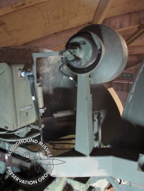
Top coating the pedestal roof edge after its repair, fitting rivnuts to replace missing captive nuts on the bearing Ward Leonard cover, preparing the internals of the pedestal ready for a repaint and resealing the Inflight Reference Aerial. An accompanying image shows the current condition of the inside of the pedestal, note the main shaft that has had the lose red lead paint removed to expose a lot of the bright steel surface. Obviously red lead paint does not adhere that well to such a surface!

T86 Pedestal Aassembly wm.jpg

LCP

The simulator was run up and tested by running some engagement exercises; it remains serviceable.

It was also noted that the smell had gone; the RIFA mains filter capacitor that had probably blown in a power supply had done its worst.

Pete


Work Day 12th October 2019

T86

The pedestal roof edge repair has been profiled, gaps filled and primed. Hopefully the repair will be ‘invisible’ when finished, see accompanying photo.

T86 Pedestal Roof Edge.jpg
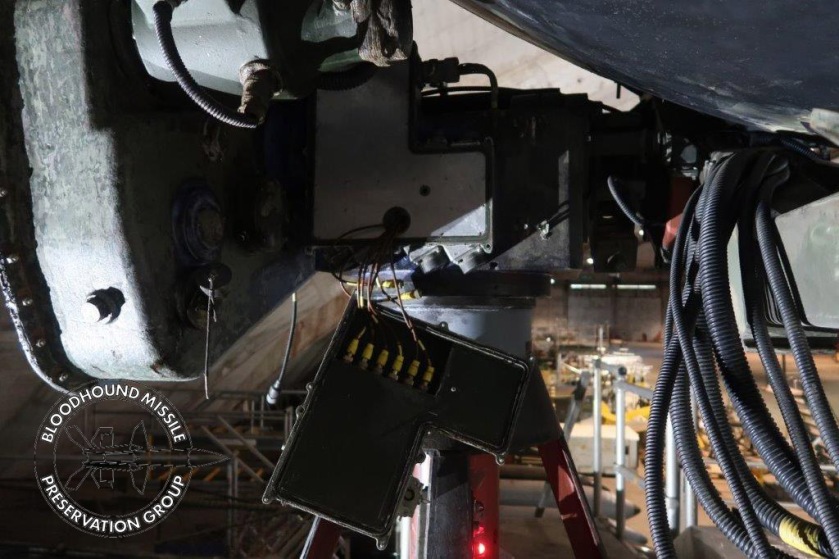
Many small restoration tasks are regularly carried out and not reported on but one example is included here. All external, steel, threaded studs will have suffered from fifty years plus exposure and the problems come when reusing these studs. The example shown in the accompanying photos show the before and after of a decking securing stud on the roof of the radar. A UNC die is run over the thread to restore it.

T86 Roof Bolt Before.jpg   T86 Roof Bolt After.jpg

As previously reported, work has started on the junction box at the top of the pedestal. The covers from the box have been removed from site to be refurbished elsewhere. A set of three accompanying photos show the condition of the covers as removed, note the corrosion and seals. One seal completely perished, the other too small and held in place with Evo Stick. The white powder corrosion is all down to the perished seal. Hopefully the covers will have been refurbished by next week.   No work was undertaken on the LCP this week.

T86 Top JB Seal.jpg

Top JB RF Connectors 1.jpg  Top JB RF Connectors 2.jpg

Pete H

Work Day 5th October 2019

T86

The main task this week was to remove the In Flight Reference Aerial. Removing the aerial allows for cleaning and preparing the hard to get to places on the aerial system before a repaint and here we have Neil hard at work!T86 Neil Disconnecting IFR Aerial wm.jpg

The following photo shows the aerial after removal and cleaning, old and perished sealant around the RFI sheet has been removed.  The In Flight and Jamming Assessment aerials will not be replaced until the repaint is completed.

T86 IFR Removed wm.jpg

Work carried out on the aerial system included corrosion treatment at the top of the pedestal. A place that has not seen any paint for a considerable time.

A couple more photos on top of the pedestal show first the top Junction Box 1 and the Elevation Motor

T86 Top Junction Box 1 wm.jpg

T86 Elevation Motor wm.jpg

LCP

The simulator was run up and remains serviceable; the photo here shows an exercise being run. Note the reflectors on the Tech Sup’s chair awaiting fitting.

LCP Displays 05_10_19 wm.jpg

Pete H

Jamming Assessment Aerial Details

With the Jamming Assessment Aerial off  it was decided to dismantle it rather than just paint it and that caused us to want to analyse how it worked; a couple of notes first:

  1. The two aerial elements (dipole and director) are on a shaft that is offset by about three degrees from the centre line so the dipoles rotate in a small circle to emulate the dipole in the missile which is seen below.12 Forebody dishwm.jpg
    Here is the aerial broken down to its invidual parts.

    08 Jamming Assess Ae Dismantledwm.jpg

    The dish itself is within the drum so the aerial assembly passes through and bolted up to the back of the dish.

  2. The  motor’s gear wheel seen here but the grease has not been dislodged from the wheel apart from where it touched a mating gear tooth. Does this mean that the aerial had not rotatated since it was last serviced, I think it does?05 Jamming Assess Ae 14wm.jpg

A couple of other observations: Corrosion is affecting the butted alloy joints, so that will be treated. The second being, the drive to the dipole shaft uses a rubber band. It was a check (six monthly?) to ensure the band hadn’t broken and I remember finding at least one that had snapped. The band on this aerial is OK burt set in a shape that again indicates it has never been running.


07 Jamming Assess Ae 7wm.jpg

06 Jamming Assess Ae 4wm.jpg
Looking at the detail of the aerial we see elements that bear some resemblance to the missile yet are very different in detail.
10 Jamming Assess Dipole 1wm.jpg
Apparently, the disk (which is flat) is called a splash plate. It seems that the distance between splash plate and dipole are critical, so perhaps the thickness of the aluminium semi-circles was selected during assembly.

The diameter of the dish is 16” (just over 40 cm) and is covered in a fibreglass case. It was noted that the displacement of the dipoles from the centre line is the radius of the metal disk in front of dipoles. If you spin the aerial the edge of the disk appears stationary at the point where the disk edge matches the centre line.

A description which looks very close to our arrangement is described here: http://armymunitions.tpub.com/mm50058/mm500580227.htm


09 Jamming Assess Ae 16wm.jpg

11 Jamming Assess Dipole 2wm.jpg

Besides the poor soldering a couple of features took us by surprise. First all elements really are electrically connected – zero ohms, even the dipole and director!  Also the size of the balance weight is quite staggering.

Here is the schematic of the aerial system, the idea of the offset aerial is shown :
Assess Ae Diagram wm.png Pete H may connect up a mains supply to see if the motor still runs. If that’s OK  he will run the motor again when reassembling and video the aerial rotating.

Mike S

28th September 2019

T86

The Jamming Assessment aerial has been removed for refurbishing, removal makes painting much easier and the joints between the aerial’s part can also be cleaned, corrosion removed and joints resealed. As can be seen here it is not in the easiest of places to access and in rather poor shape.

01 Jamming AA 1wm.jpg 02 Jamming AA 2wm.jpg

03 Jamming AA 3wm.jpg

04 JAA before wm.jpg

See the accompanying photo of the aerial parts after receiving their first coat of paint. Also included in the photo are covers from the elevation synchros.

14 T86 Parts Restoration JA Ae + Coverswm.jpg

After being stored under the radar for a few years the covers from the base of the pedestal have been cleaned, engrained dirt and the odd streak of grease being removed. Accompanying photo shows the results.

13 T86 Cover under Pedesatalwm.jpg

The technical aspects of this aerial are as interesting as they are puzzling and will be covered in a separate blog.

LCP

The simulator was run up and remains serviceable.

For the last two test runs an ‘electronic’ type smell has emanated from the computer rack. The smell is possibly from blown mains filter RIFA capacitors in a power supply. These capacitors have a dielectric that can boil due to age related cracks in their casing, they do not prevent the power supply from working. A job for this winter beckons … find which of the eleven power supplies is at fault!

Pete